Welcome, reader, to my first article and the first part of a 3-part (maybe 4-part) series. This series will be focused on wiring up a toy robot arm with an Arduino used to replace the controller. I’ll be doing my best to keep this all as readable as possible, and to be open about the challenges I face. Most builder blogs focus on what the right choices are and how to replicate them exactly. I think it’s helpful to also look at the mistakes I made along the way, and help you understand why I’m NOT doing something. To get the most out of these articles it is best to have some basic programming experience, and at least enough electrical knowledge to understand how to spin a DC motor with a battery.
This first post will be dedicated to looking at what we need to build our Arduino controlled robot arm. With that in mind, let’s dive into the materials.
The Robot Arm

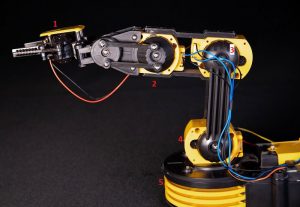
The robot arm used in this project
First up is the arm I used, available from Sayal Electronics, part number CIC21-535. It’s a toy that requires some assembly, and I have no datasheet or specifications for it. A lot of the fun in a project like this is taking something you find and know almost nothing about, that looks like it might be useful, and just seeing if you can do anything with it.
The best part of this arm is that every motor’s two control wires are bound by a connector which is easy to work with and is a good fit for stripped wire. The spin motor (5 in the image above) is the only one that has its control wires hidden, but it’s just takes removing one screw to access the connector underneath the yellow shell.
The worst part is the mechanical braking system they use to keep the motors locked in place. It may seem like a bonus at first for those of you who have worked with a DC motor before because you don’t have to worry about deceleration and drift (or feedback from manually moving motors). Instead it causes a lot of friction when trying to move the motors and really limits them at low speed.
The Arduino

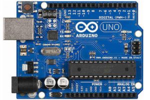
One version of the Arduino Uno
I used an Arduino Uno for this project. The Uno is easy to use, easy to program, big enough to give you a good pin selection, and small enough to put into an actual build. It’s a great platform for prototyping small projects ranging from moving a mechanical arm to controlling LED lighting in an art project. Programming for the device is also simple and meant to be understandable by people without coding experience.
The important part for this project is that the Uno gives us the use of several PWM pins. These pins are what allow for control of the speeds of the motors. By turning the pin on and off quickly, the Arduino can output an average voltage somewhere between 0V and 5V depending on the setting, which in turn controls how much power is actually delivered from the battery to the motor through the quadruple half-h bridge.
The Quadruple Half-H Bridge

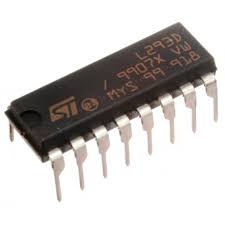
ST Micro L293D Quad Half-H Bridge
This is the chip that will let the us power the motor with a 9V battery and separate it from the Arduino’s power supply. It also simplifies control of the direction of the motor by giving us access to a pair of control pins which handle the switching of positive and ground for the motor control wires. Depending on the chip you use it may also offer feedback protection from the motor, protecting the Arduino. Because of the mechanical braking on the arm’s motors in this case feedback isn’t really a concern though.
The Other Stuff
The other parts we’ll need for this project are the 9V lead battery, a pushbutton, a resistor, a breadboard, lots of colorful wires, and a wire stripper for stripping and cutting them. The 9V lead battery is not mandatory if you don’t have one sitting around like I happened to. You can take power from the four D cell batteries that normally power the arm, the wires leading from the batteries to the board where the controller plugs in have the same connector as the motor wires, making it easy connect to the breadboard’s power strip. It will add some time when you’re testing the Arduino as a controller, because you need to reattach the power supply to use the standard controller when repositioning the arm. I would not recommend using the Arduino to power the motors, even if the Arduino could output the 6V the motors are looking for, you risk drawing too much amperage.
You will also need to download the Arduino IDE in order to edit the program and upload it to your own Arduino board. The most recent version can be found from the Arduino website here.
Final Thoughts
That’s it for my first post, hopefully you can start to see what we’ll be building over the course of the next couple of articles in this series. I’m excited to share the initial build and code with you next!
